


Models
>
91136655792
91136655792 Kenmore Range
Jump to:
Find Part by Name
Keep searches simple, eg. "belt" or "pump".
Manuals & Guides for 91136655792
Click to downloadKeep searches simple, eg. "belt" or "pump".

$21.95
This 40-Watt light bulb is sold individually.
It is specially designed to withstand extreme temperatures, so this bulb is compatible with a variety of appliance types including refrigerators, ranges,...
In Stock
Order now and your part arrives by Jul 30

In Stock
Order now and your part arrives by Jul 30

In Stock
Order now and your part arrives by Jul 30

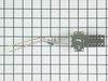
$43.92
This is a broiler pan for your range. It catches drippings from the cookware, when broiling in the oven. This assembly includes the grill/grate and the bottom pan. These parts are made of porcelain. T...
In Stock
Order now and your part arrives by Jul 30

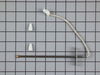
$52.75
This part sits on top of the valve. Once the knob is turned it will create a spark that will light the gas and start the burner.
In Stock
Order now and your part arrives by Jul 30


In Stock
Order now and your part arrives by Jul 30

In Stock
Order now and your part arrives by Jul 30

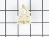
This orifice spud changes the burner from natural gas, to liquid propane. This orifice is sold individually.
No Longer Available


In Stock
Order now and your part arrives by Jul 30

Common Problems and Symptoms for 91136655792
Viewing 6 of 6Little to no heat when baking
Fixed by these parts
How to fix it
Will Not Start
Fixed by these parts
How to fix it
Oven not heating evenly
Fixed by these parts
How to fix it
Oven is too hot
Fixed by these parts
How to fix it
Gas igniter glows, but will not light
Fixed by these parts
How to fix it
Element will not heat
Fixed by these parts
How to fix it

Keep searches simple. Use keywords, e.g. "leaking", "pump", "broken" or "fit".
- Customer:
- James from Austin, TX
- Parts Used:
- WB21X5301
- Difficulty Level:
- Easy
- Total Repair Time:
- 1- 2 hours
- Tools:
- Nutdriver, Screw drivers
Oven tempature was approximately 150 degrees to low
This repair is EASY if you know how to use an ohm meter. If not, seek help for this step.
SYMPTOM:
The oven (JKP27WOP3WG or JKP27WP3WG and many ovens like it ) was not getting hot enough. Verifying the cooking temperature with an typical oven thermometer, I was able to determine that the oven was cooking temperature was ... Read more about 150 degrees to low.
FAILURE POINTS:
There are two logical failure points (1) The oven sensor ( WB21X5301 about $75), or the (2) the controller board (PS238233 about $252). In my case it was the controller board. When replaced the oven worked beautifully.
REPAIR:
As with any repair, you MUST DISCONNECT POWER TO THE UNIT BEFORE SERVICING!!!
Pull oven from the wall:
- Disconnect power by flipping the circuit breaker to the OFF position.
- Remove the top flange / cowling from the top of the oven (it just pulls off)
- Remove two screws under the top flange / cowling
- The whole unit easily slides out, but it is highly recommended that you use two people to place the oven on the floor.
As a diagnostic between these two parts, if the oven sensors measure approximately 1.1K ohms of resistance at room temperature, then it is probably not the sensor. The oven sensor wires are connected to two white wires that run up to the controller board. You need to disconnect the oven sensor to make the measurement. You may either completely remove the oven sensor by cutting the wire (be sure to allow yourself enough slack so that they may be safely reconnected) where it connects to the white wires, OR, (preferred method) if leaving the oven sensor partially installed,
- Remove the top sheet metal cover (10 screws)
- Remove the service connect cover (2 screws - this is where the main Power cord comes into the unit)
- Disconnect the white wires from the controller board (this connector which also includes other circuits is on the left side when looking at the controller board).
- Remove two screws from oven sensor but just let in dangle down so that you can put the sensor in the ice water / boiling water.
Measure the resistance under the following conditions. Your ohm meter should read APPROXIMATELY...
- 1.02K ohms in ice water
- 1.09K ohms at room temperature
- 1.36K ohms in boiling water.
If you get approximately these readings, then it is NOT the oven sensor. If that checks out then re-install the sensor AND the connector.
If it is NOT the sensor, replace the controller board.
- Take a moment to write down the color of the wire to the LETTERING (N, L, G, C / COM,,,) on the controller board. The connectors are in different locations on the new controller board so the wire color to the letter designation is significant.
- Carefully remove the wires one at a time
- VERY carefully remove the keypad ribbon cable from the right side of the controller board.
-- The ribbon cable will disconnect by releasing some little pressure clips on the side of the connector.
- Remove the controller board (4 screws)
- Install new controller board (4 screws)
- VERY carefully connect the keypad ribbon cable on the right side.
-- Make sure that the connector is in the OPEN position first, then,
-- Slide in the cable ensuring that all parts of the ribbon made it into the connector, then
-- Press down on the connector locking tabs.
- Reconnect each wire to the correctly lettering on the board.
-- Again, the connectors MAY BE in a different order on the replacement controller board. Match color to letter.
- Reconnect the (5 wire?) connector that includes the white oven sensor wires.
- Make sure everything looks normal, (i.e. no wires are pinched, remove tools from top of oven area, etc.)
- Re-install top cover.
- Re-install service connect cover.
You can test the unit while it is out of the cabinet,
- Make SURE that all sheet metal covers are in place.
- Flip power breaker to "On".
- Test that oven gets to the desired temp.
Read less
Was this instruction helpful to you?
Thank you for voting!
- Customer:
- Michael from Lawrenceville, GA
- Parts Used:
- WB21X5301
- Difficulty Level:
- Really Easy
- Total Repair Time:
- Less than 15 mins
- Tools:
- Screw drivers
Oven would not heat to the correct temperature
First I removed the two screws that hold the element in place. I then pulled the element out about 3 inches and disconnected the two wires
Was this instruction helpful to you?
Thank you for voting!
- Customer:
- Joseph from Brick, NJ
- Parts Used:
- WB21X5301
- Difficulty Level:
- A Bit Difficult
- Total Repair Time:
- 30 - 60 mins
- Tools:
- Nutdriver, Pliers
F2 error message on my GE oven indicated need for new heat sensor
After unscrewing the old heat sensor from inside the oven, I pulled the range away from the wall, got behind it and removed the small panel over the heat sensor. Naturally, the plastic clips connecting the heat sensor to the range wiring wouldn't come apart, so I eventually had to simply pry them apart with two pliers. Then, naturally, th
... Read more
e new plastic connector clip on the replacement part didn't match the clip from the range, so I had to cut off both receptacles and strip the wires, then used the provided wire nuts to make the connections. After that, it was easy, just secured the heat sensor inside the oven and replaced the panel. I didn't push the range back against the wall until I tested the repair. It worked fine!
Read less
Was this instruction helpful to you?
Thank you for voting!