


Models
>
JM250DF3BB
JM250DF3BB General Electric Range
Jump to:
Find Part by Name
Keep searches simple, eg. "belt" or "pump".
Diagrams for JM250DF3BB
Viewing 4 of 4


Keep searches simple, eg. "belt" or "pump".

$21.95
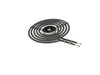
This is a genuine replacement drip bowl, that measures 6 inches in internal diameter to match the burner, but actually measures closer to 8 inches in diameter in total to its outer edge. If this part ...
In Stock
Order now and your part arrives by Aug 2

$26.95
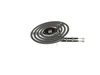
This is a 10-inch chrome drip bowl intended to fit an 8-inch burner. This bowl is used to catch drips from food cooking on the oven element. This bowl might burn, become rusty, and just generally wear...
In Stock
Order now and your part arrives by Aug 2

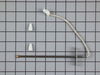
This metallic clip is used to help support the broil element. Sold individually.
In Stock
Order now and your part arrives by Aug 2

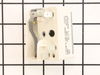
This infinite switch controls the heat level of a 6-inch, 1560-watt surface element by regulating power flow. It operates at 240 volts and helps maintain consistent temperatures. Replacing it can fix ...
In Stock
Order now and your part arrives by Aug 2

In Stock
Order now and your part arrives by Aug 2

In Stock
Order now and your part arrives by Aug 2

In Stock
Order now and your part arrives by Aug 2

In Stock
Order now and your part arrives by Aug 2

In Stock
Order now and your part arrives by Aug 2

$61.55
This part provides a way of connecting individual electrical wires and offers protection of the device from electrical surges (voltages and/or currents).
In Stock
Order now and your part arrives by Aug 2

In Stock
Order now and your part arrives by Aug 2

In Stock
Order now and your part arrives by Aug 2
Common Problems and Symptoms for JM250DF3BB
Viewing 5 of 5Element will not heat
Fixed by these parts
How to fix it
Little to no heat when baking
Fixed by these parts
How to fix it
Will Not Start
Fixed by these parts
How to fix it
Oven not heating evenly
Fixed by these parts
How to fix it
Oven is too hot
Fixed by these parts
How to fix it


Keep searches simple. Use keywords, e.g. "leaking", "pump", "broken" or "fit".
- Customer:
- Tom from North Prairie, WI
- Parts Used:
- WB31T10011, WB31T10010
- Difficulty Level:
- Really Easy
- Total Repair Time:
- Less than 15 mins
Burner bowls needed replacement
Very easy repair, Pulled burner coil out, removed old burner bowl. Put in new burner bowl, plugged burner coil back in... easy as 1,2,3
Was this instruction helpful to you?
Thank you for voting!
- Customer:
- Stephen from Knoxville, TN
- Parts Used:
- WB31T10011, WB31T10010
- Difficulty Level:
- Really Easy
- Total Repair Time:
- Less than 15 mins
Burner Bowl Needed Replaced
Removed burner element and put in bowl
Was this instruction helpful to you?
Thank you for voting!
- Customer:
- James from Austin, TX
- Parts Used:
- WB21X5301
- Difficulty Level:
- Easy
- Total Repair Time:
- 1- 2 hours
- Tools:
- Nutdriver, Screw drivers
Oven tempature was approximately 150 degrees to low
This repair is EASY if you know how to use an ohm meter. If not, seek help for this step.
SYMPTOM:
The oven (JKP27WOP3WG or JKP27WP3WG and many ovens like it ) was not getting hot enough. Verifying the cooking temperature with an typical oven thermometer, I was able to determine that the oven was cooking temperature was ... Read more about 150 degrees to low.
FAILURE POINTS:
There are two logical failure points (1) The oven sensor ( WB21X5301 about $75), or the (2) the controller board (PS238233 about $252). In my case it was the controller board. When replaced the oven worked beautifully.
REPAIR:
As with any repair, you MUST DISCONNECT POWER TO THE UNIT BEFORE SERVICING!!!
Pull oven from the wall:
- Disconnect power by flipping the circuit breaker to the OFF position.
- Remove the top flange / cowling from the top of the oven (it just pulls off)
- Remove two screws under the top flange / cowling
- The whole unit easily slides out, but it is highly recommended that you use two people to place the oven on the floor.
As a diagnostic between these two parts, if the oven sensors measure approximately 1.1K ohms of resistance at room temperature, then it is probably not the sensor. The oven sensor wires are connected to two white wires that run up to the controller board. You need to disconnect the oven sensor to make the measurement. You may either completely remove the oven sensor by cutting the wire (be sure to allow yourself enough slack so that they may be safely reconnected) where it connects to the white wires, OR, (preferred method) if leaving the oven sensor partially installed,
- Remove the top sheet metal cover (10 screws)
- Remove the service connect cover (2 screws - this is where the main Power cord comes into the unit)
- Disconnect the white wires from the controller board (this connector which also includes other circuits is on the left side when looking at the controller board).
- Remove two screws from oven sensor but just let in dangle down so that you can put the sensor in the ice water / boiling water.
Measure the resistance under the following conditions. Your ohm meter should read APPROXIMATELY...
- 1.02K ohms in ice water
- 1.09K ohms at room temperature
- 1.36K ohms in boiling water.
If you get approximately these readings, then it is NOT the oven sensor. If that checks out then re-install the sensor AND the connector.
If it is NOT the sensor, replace the controller board.
- Take a moment to write down the color of the wire to the LETTERING (N, L, G, C / COM,,,) on the controller board. The connectors are in different locations on the new controller board so the wire color to the letter designation is significant.
- Carefully remove the wires one at a time
- VERY carefully remove the keypad ribbon cable from the right side of the controller board.
-- The ribbon cable will disconnect by releasing some little pressure clips on the side of the connector.
- Remove the controller board (4 screws)
- Install new controller board (4 screws)
- VERY carefully connect the keypad ribbon cable on the right side.
-- Make sure that the connector is in the OPEN position first, then,
-- Slide in the cable ensuring that all parts of the ribbon made it into the connector, then
-- Press down on the connector locking tabs.
- Reconnect each wire to the correctly lettering on the board.
-- Again, the connectors MAY BE in a different order on the replacement controller board. Match color to letter.
- Reconnect the (5 wire?) connector that includes the white oven sensor wires.
- Make sure everything looks normal, (i.e. no wires are pinched, remove tools from top of oven area, etc.)
- Re-install top cover.
- Re-install service connect cover.
You can test the unit while it is out of the cabinet,
- Make SURE that all sheet metal covers are in place.
- Flip power breaker to "On".
- Test that oven gets to the desired temp.
Read less
Was this instruction helpful to you?
Thank you for voting!