


Models
>
AKT3040WW-10
AKT3040WW-10 Amana Range
Jump to:
Find Part by Name
Keep searches simple, eg. "belt" or "pump".
Keep searches simple, eg. "belt" or "pump".

In Stock
Order now and your part arrives by Aug 6

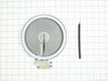
This surface element is made for under glass set-ups and supplies the heat to a cooking area on top of the range. It has an outside diameter of approximately 7 inches (1500 watts), and is a genuine OE...
In Stock
Order now and your part arrives by Aug 6

$75.36
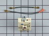
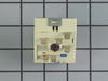
This is an OEM part sourced directly from Amana. This surface infinite element switch is commonly used in ranges and cooktops. This switch is designed to turn the surface element on and off, as well a...
In Stock
Order now and your part arrives by Aug 6

In Stock
Order now and your part arrives by Aug 6

Special Order

Special Order

This is an authentic OEM replacement part. This is a radiant surface element used on ranges and cooktops. It is a 6-inch element designed for use with the small burners on your cooktop. This surface r...
No Longer Available

Special Order

Special Order
Common Problems and Symptoms for AKT3040WW-10
Viewing 2 of 2Element will not heat
Fixed by these parts
How to fix it
Will Not Start
Fixed by these parts
How to fix it

Keep searches simple. Use keywords, e.g. "leaking", "pump", "broken" or "fit".
- Customer:
- Michael from Collierville, TN
- Parts Used:
- 12002125
- Difficulty Level:
- A Bit Difficult
- Total Repair Time:
- 30 - 60 mins
- Tools:
- Nutdriver, Pliers, Socket set
Outer element of dual element burner didn't work
Remove Ceran Galss top by removing hex screws below the rim. Also remove the two opposing screws in the center of the downdraft opening. Ceran top comes off easily now.
The instructions with the new switch were very poorly written, so here is how I got the new switch to work:
Attach the black wire(s) from the old switch (termi ... Read more nal 2) to the new switch terminal P1. Also attach the jumper cable to P1 and "jump" it to S1.
Attach the orange wire (old switch terminal 5) to S2
Attach the yellow wire (old switch terminal 4) to 4a
Attach the tan/(white?) wire (old switch terminal 3) to terminal 4 on the new switch
Attach the single red wire from the right front element to terminal 2 on the new switch.
Attach the 'compound' red wires (the ones that come from the left rear/outlet connection and is also attached to the right rear switch) to terminal P2 on the new switch.
There is no need to seperate the compound red wires as the instructions might lead you to believe.
Good Luck
Read less
Was this instruction helpful to you?
Thank you for voting!
- Customer:
- Igor from Campbell, CA
- Parts Used:
- 12002125
- Difficulty Level:
- Really Easy
- Total Repair Time:
- 15 - 30 mins
- Tools:
- Nutdriver, Pliers, Screw drivers
The repair itself was very easy. “How to connect” was very hard to get.
The repair itself was very easy. “How to connect” was very hard to get.
To get access to the switch, unscrew 2 screws from each side of front panel and then 4 screws from the bottom of it (open the door first). Have a box or a small table about 30” high to use it as support for the front panel.
The end result ... Read more (colors for the Right Front- R.F.- burner) : Old label -> New label
1. Double RED: N -> P2 (incoming power, Line 1)
2. Single RED: N -> 2 (to Inner AND Outer heating elements common wire)
3. Single BLK: L1 -> P1 (incoming power, Line 2)
4. Single TAN: H1 -> 4 (to the Inner heating element)
5. Single YEL: H2-> 4a (to the Inner heating element)
6. Single BLK: P -> S2 (to the R.F. indicator control light)
7. Attach jumper black wire (included with new switch) from P1 (P1 has two connectors close together) to S1.
Done.
Read less
Was this instruction helpful to you?
Thank you for voting!
- Customer:
- Todd from Concord, OH
- Parts Used:
- 12002125
- Difficulty Level:
- A Bit Difficult
- Total Repair Time:
- 30 - 60 mins
- Tools:
- Nutdriver
Jenn Air Dual element switch broke
This is not at hard as it seems; I followed the first guy's story and ignored the colors because mine were different. I did have to split the combined red wires, intimidating at first but once I split them it was down hill.
I did have to use the jumper wire.
Follow
Appliance Repaired: Jenn-Air Range/Stove/Oven/H ... Read more ood
Model: cve3401b
Age Of Appliance: 5 - 10 years
Remove Ceran Galss top by removing hex screws below the rim. Also remove the two opposing screws in the center of the downdraft opening. Ceran top comes off easily now.
The instructions with the new switch were very poorly written, so here is how I got the new switch to work:
Attach the black wire(s) from the old switch (terminal 2) to the new switch terminal P1. Also attach the jumper cable to P1 and "jump" it to S1.
Attach the wire from old switch terminal 5)to S2
Attach the wire from old switch terminal 4 to 4a
Attach the wire from old switch terminal 3 to terminal 4 on the new switch
Detach the 'compound' red wires from each other.
(The ones that come from the left rear/outlet connection and is also attached to the right rear switch) to terminal P2 on the new switch.
I attached common female connectors.
Attach the newly split single red wire from the right front element to terminal 2 on the new switch.
One note:
Before you remove the four screws that hold the four swtiches down make sure that you use a sharpie and mark the switchbox location. You will notice that it is difficult to get them to line up again with the holes in the cooktop.
Thanks partselect.com!
Read less
Was this instruction helpful to you?
Thank you for voting!