



Models
>
JP385BD1BB
JP385BD1BB General Electric Cooktop
Jump to:
Find Part by Name
Keep searches simple, eg. "belt" or "pump".
Diagrams for JP385BD1BB
Viewing 1 of 1
Keep searches simple, eg. "belt" or "pump".
$22.91
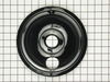
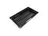
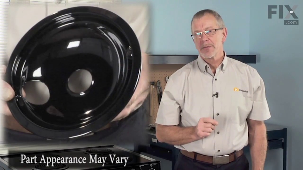
This burner bowl, also known as a drip bowl, is an authentic OEM part for your electric range or cooktop. This part is black in color and designed to fit under the 8-inch coiled burner elements and is...
In Stock
Order now and your part arrives by Oct 15
$18.95
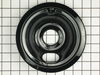
This genuine OEM burner bowl, also known as a drip tray, is black and color and measures 6 inches in diameter. It is designed to be used under the coiled elements on an electric stove or range, in ord...
In Stock
Order now and your part arrives by Oct 15
$45.95
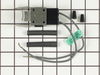
This kit includes one ceramic block with 6" wire leads, 2 wire nuts and 2 heat shrink with mounting bracket.
In Stock
Order now and your part arrives by Oct 15
In Stock
Order now and your part arrives by Oct 15
Special Order

Common Problems and Symptoms for JP385BD1BB
Viewing 1 of 1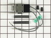
Keep searches simple. Use keywords, e.g. "leaking", "pump", "broken" or "fit".
- Customer:
- Jack from Steamboat Springs, CO
- Parts Used:
- WB23X10009, WB03X10089
- Difficulty Level:
- Easy
- Total Repair Time:
- 15 - 30 mins
- Tools:
- Pliers, Screw drivers
Knob-shaft on element switch broke
***** Unplug the stove *****
1. Removed all knobs, including knobs for other elements and exhaust fan. Because there was years of oil build-up, I used a screwdriver to gently pry off the knobs from the shaft.
2. Remove lock nut from all switches using pliers to first loosen the nuts. Once loosened, I used my fingers to remove th ... Read more e nuts.
3. Remove the rubber gaskets from the element switches, NOT the exhaust fan switch. The exhaust knob gasket is part of the larger glass cover-plate gasket.
4. Remove the glass cover plate to expose the switches. There were two phillips screws to secure the switch plate to the electrical box. Took those off to access the switch.
5. Made a quick sketch of the electrical connections.
6. Removed the damaged switch and the electrical connections.
7. Connected electrical wires to new switch and installed new switch.
8. Took the opportunity to thoroughly clean the glass cover plate and gaskets.
9. Screwed the switch plate back onto the electrical box.
10. Put back glass plate and reinserted the knob gaskets.
11. Put back the lock nuts. Used fingers to tighten then used pliers to give it another quarter turn, making sure not to over tighten.
12. Replaced knobs.
13. Plugged in stove and tested.
Start to finish, it took about 15-20 minutes (mostly due to the cleaning).
1. Removed all knobs, including knobs for other elements and exhaust fan. Because there was years of oil build-up, I used a screwdriver to gently pry off the knobs from the shaft.
2. Remove lock nut from all switches using pliers to first loosen the nuts. Once loosened, I used my fingers to remove th ... Read more e nuts.
3. Remove the rubber gaskets from the element switches, NOT the exhaust fan switch. The exhaust knob gasket is part of the larger glass cover-plate gasket.
4. Remove the glass cover plate to expose the switches. There were two phillips screws to secure the switch plate to the electrical box. Took those off to access the switch.
5. Made a quick sketch of the electrical connections.
6. Removed the damaged switch and the electrical connections.
7. Connected electrical wires to new switch and installed new switch.
8. Took the opportunity to thoroughly clean the glass cover plate and gaskets.
9. Screwed the switch plate back onto the electrical box.
10. Put back glass plate and reinserted the knob gaskets.
11. Put back the lock nuts. Used fingers to tighten then used pliers to give it another quarter turn, making sure not to over tighten.
12. Replaced knobs.
13. Plugged in stove and tested.
Start to finish, it took about 15-20 minutes (mostly due to the cleaning).
Read less
Was this instruction helpful to you?
Thank you for voting!
- Customer:
- PATRICK from WASHINGTON, DC
- Parts Used:
- WB17X5113
- Difficulty Level:
- Easy
- Total Repair Time:
- 15 - 30 mins
- Tools:
- Screw drivers
I had 2 of the terminals where the burner coil plugs into completely fry
First thing to do is to KILL THE POWER. The last thing you want is for two leads feeding power to a range coil burner "hot" when you are working on them. After power is off, I removed the coils and set them aside. The terminals had "fried" apparently from to much cooking with hot oils and having the "over splash" working its way down t
... Read more
o where the coils plug into the terminals and over time the oil getting in the terminals causes shorting / frying of the leads / contacts.
Anyway, after removing the heat coils I removed the drip pans and cleaned up the area underneath before working on terminals. I like a clean area when I work. I then unscrewed the "brackets" that house the terminals with a Phillips screwdriver and pulled out the assembly.
To completely remove the assembly I cut with a straight razor the existing heat shrink around the wire nuts (These two had been replaced once before. On first go around, I just cut the terminal assembly off and stripped the wire to attach the new terminals). Then I removed the wire nuts and the old assembly. After that I trimmed the wire to the correct length on the new terminal assembly and checked that the wire from the stove was in good shape. Upon confirming I had a good lead, I connected the new terminal leads to the stove leads and put the heat shrink over the connections. I used a lighter to "shrink" the heat shrink to the new connection (not having a proper heat shrink gun, which most of us don't have, the lighter works well as long as you are careful and do not let the lighter heat up to much. Let the lighter cool (esp. if a plastic disposable type or it will melt and ruin the lighter or burn your fingers).
After that I cleaned the area where the terminal block bracket connects to the stove (it gets a bit gunked up over time) before screwing in the new bracket / assembly in place with my screwdriver.
I gave the drip pans a good cleaning, adjusted the new terminal brackets so they were even / centered, cleaned once more the area under the drip pan and replaced the drip pans. The types of pans I have are one piece with a hole for the heat coil leads to go through.
Before placing the coils back in the terminals I took a strip of medium grade, 220 grit, sand paper (you could use steal wool or small wire brush) and cleaned the terminal leads (the steal end that plugs into the terminal only, careful not to damage the burner). This was needed as the leads had accumulated some residue from the same dynamics that caused the burning / melting of the terminal leads and terminal block. Once the leads were clean I fitted them into the place in the new terminal blocks and drip pan grooves.
Finally I turned back on the breaker to the stove and cranked on the burners to test out the connection and that everything was working A-OK.
Job done:-)
Anyway, after removing the heat coils I removed the drip pans and cleaned up the area underneath before working on terminals. I like a clean area when I work. I then unscrewed the "brackets" that house the terminals with a Phillips screwdriver and pulled out the assembly.
To completely remove the assembly I cut with a straight razor the existing heat shrink around the wire nuts (These two had been replaced once before. On first go around, I just cut the terminal assembly off and stripped the wire to attach the new terminals). Then I removed the wire nuts and the old assembly. After that I trimmed the wire to the correct length on the new terminal assembly and checked that the wire from the stove was in good shape. Upon confirming I had a good lead, I connected the new terminal leads to the stove leads and put the heat shrink over the connections. I used a lighter to "shrink" the heat shrink to the new connection (not having a proper heat shrink gun, which most of us don't have, the lighter works well as long as you are careful and do not let the lighter heat up to much. Let the lighter cool (esp. if a plastic disposable type or it will melt and ruin the lighter or burn your fingers).
After that I cleaned the area where the terminal block bracket connects to the stove (it gets a bit gunked up over time) before screwing in the new bracket / assembly in place with my screwdriver.
I gave the drip pans a good cleaning, adjusted the new terminal brackets so they were even / centered, cleaned once more the area under the drip pan and replaced the drip pans. The types of pans I have are one piece with a hole for the heat coil leads to go through.
Before placing the coils back in the terminals I took a strip of medium grade, 220 grit, sand paper (you could use steal wool or small wire brush) and cleaned the terminal leads (the steal end that plugs into the terminal only, careful not to damage the burner). This was needed as the leads had accumulated some residue from the same dynamics that caused the burning / melting of the terminal leads and terminal block. Once the leads were clean I fitted them into the place in the new terminal blocks and drip pan grooves.
Finally I turned back on the breaker to the stove and cranked on the burners to test out the connection and that everything was working A-OK.
Job done:-)
Read less
Was this instruction helpful to you?
Thank you for voting!
- Customer:
- Louis from Sandwich, MA
- Parts Used:
- WB31T10015, WB31T10014
- Difficulty Level:
- Really Easy
- Total Repair Time:
- Less than 15 mins
aged burner bowls
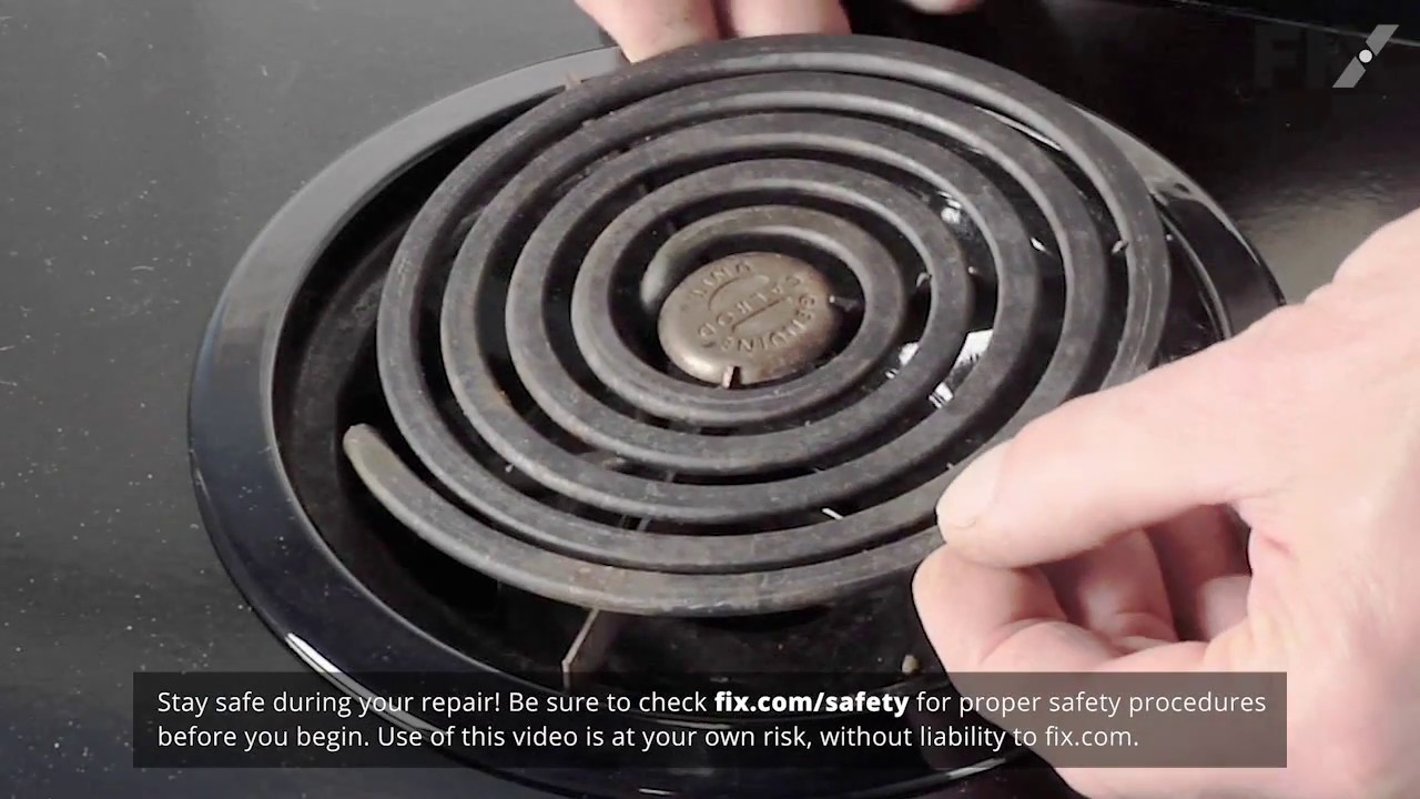
I just removed the range elements and old bowls, placed the new bowls into the range top, and inserted the heating elements. What surprised me was the quickness in filling the order. I had the new parts the next day! Great!
Was this instruction helpful to you?
Thank you for voting!